AWS Gateway Load Balancer (GWLB) offers a new approach for integrating third-party virtual appliances on AWS. There are many excellent articles on setup details and traffic flows. However, I find it overwhelming to decipher AWS route tables without high-level pictures. This blog provides my interpretation of GWLB used in the context of firewall integration.
Introduction
Figure 1 illustrates the problem to solve in the simplest form. There’s a source and destination with network reachability. Now the requirement is to inspect traffic between the two.
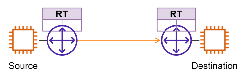
In the traditional approach, a firewall device is deployed in Layer3 mode somewhere along the path. The left side is treated as one security zone and the right side as another. In a Public Cloud environment, this approach faces several challenges. Underlying virtual machines used for VNFs normally have a limited number of network interfaces. More importantly, Public Clouds don’t offer the same L2/L3 network protocols as on-prem for high availability NFV designs. Cloud providers need to keep their network offers “simple” enough to scale massively.
The Building Blocks
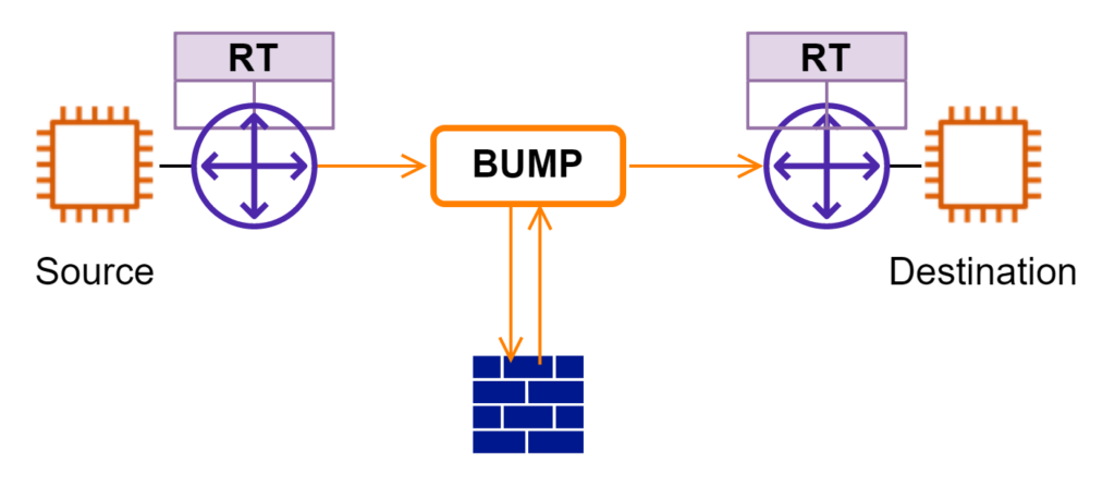
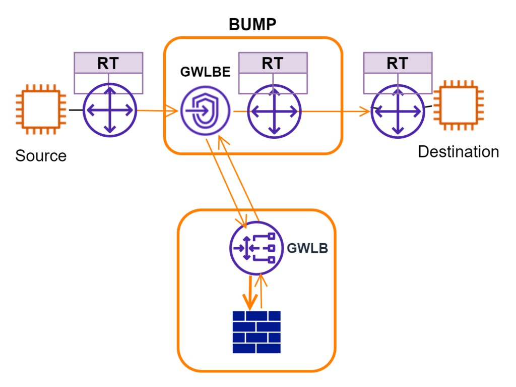
GWLB is also described as bump-in-the-wire. It reminds me of service function chaining (SFC) or service insertion I worked on a few years ago. Network traffic is sent to a “bump” first. The “bump” is programmed to forward traffic to other VNFs for additional processing. In the end, traffic returns to “bump” and continues downstream the network path. In this model, VNF (ie firewall in this case) is decoupled from L3 routing. If AWS were to offer yet another new network service in the future to connect workloads, I do not need to “rewire” my firewalls.
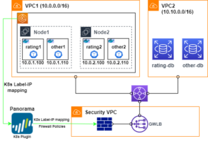
In Figure 3, I separate components for GWLB integration into two buckets. The lower box includes GWLB and virtual firewall appliances. This bucket is easier to grasp. Traffic is forwarded into GWLB and load-balanced over a fleet of firewall appliances. Overlay technology (GENEVE) is used to reserve source and destination address information for traffic inspections.
The “BUMP” bucket takes a little time to digest. To route traffic from source to destination, there are two AWS route tables to consider. The Route table to the left of “BUMP” needs to have a route covering the destination address. GWLBE is configured as the next hop. For the Route table that “GWLBE” is attached to, it needs to have a record that is used to forward traffic downstream. For return traffic, the Route table to the right of “BUMP” needs to have a record covering the source address with GWLBE as the next hop. The “BUMP”/GWLBE is typically deployed in the same VPC as the source. The BUMP’s RT should have its VPC CIDR as next-hop local already.
Flow Inspections
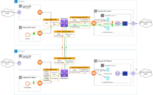
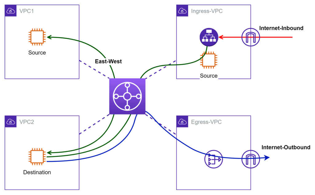
Before I get into deployment details about how firewall works together with GWLB, let’s review common AWS network patterns. In Figure 4, I use four VPCs to illustrate the high-level idea. VPC1 and VPC2 are both internal. Traffic between VPC1/2 is considered East-West. Ingress-VPC contains IGW and AWS load balancers that front internet ingress traffic. Egress-VPC provides a shared exit point for outbound internet traffic.
Now let’s examine how to drop “BUMP”s onto the above setup for inspection of different flows.
Isolated Design Model
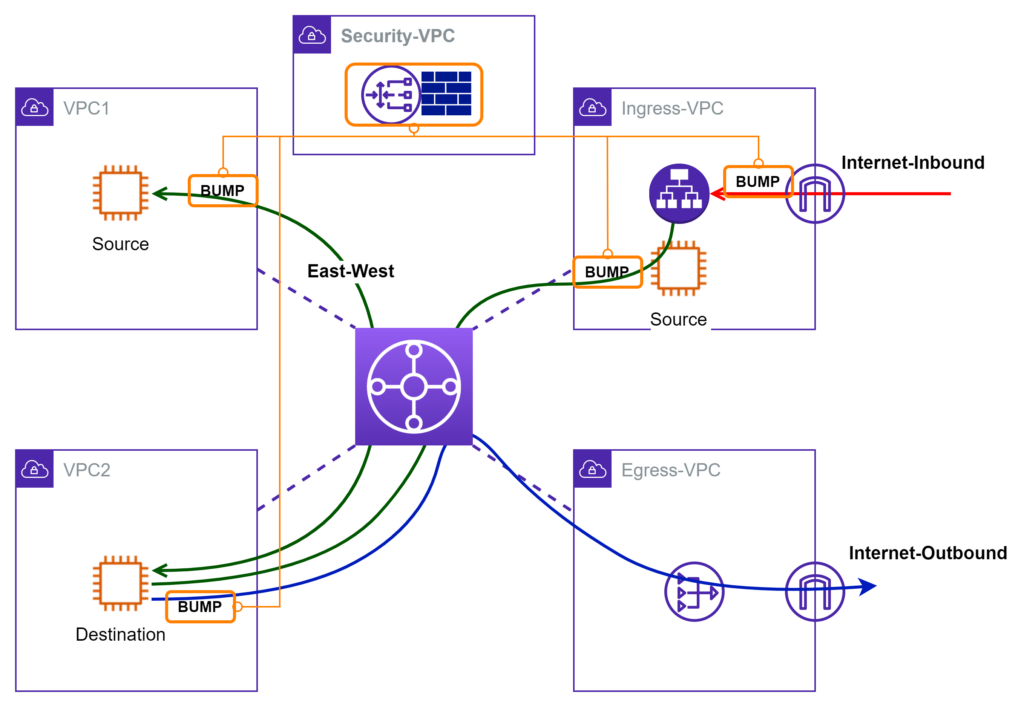
I am borrowing the “isolated” term from Palo Alto. In this model, the “BUMP” is deployed closer to source workloads. For example, it is desired to inspect internet ingress traffic right after IGW. I simply visualize it as placing a “BUMP” in-between IGW and LB. If there’s also a requirement to inspect traffic leaving Ingress-VPC (if Ingress-VPC is considered as DMZ), I put another “BUMP”. The same visualization idea can be applied to workloads that are subject to East-West and Outbound inspections.
With this model, traffic coming out of “BUMP” does not go through TGW. This translates to saving from the TGW traffic volume charge. Since TGW RT is not involved, there is much less chance to impact other VPC traffic unintentionally. There are fewer LOGICAL network hops to cross. Troubleshooting is much easier, especially if multiple AZs are involved. More importantly, it demonstrates the flexibility of enforcement-point placement using this bump-in-the-wire approach.
Centralized Design Model
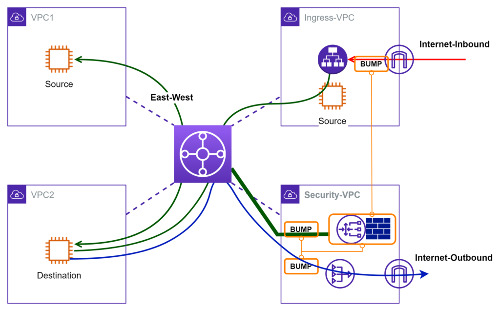
Again, I borrow the term from Palo Alto. If most of the traffic traverses through TGW, then TGW is a good place to divert traffic into the “BUMP”s for inspection. Conceptually, I visualize a magical “BUMP” hidden inside TGW that forwards traffic to firewall appliances. In real implementation, TGW route table is programmed to forward traffic into the Security VPC. Inside Security VPC, traffic hairpins through BUMP, GWLB, Firewall appliance, then returns to TGW. As the VPC number grows, the centralized design is a more scalable solution to manage.
Takeaways
AWS GWLB offers a new way for VNF deployment. It decouples AWS routing from security functions. However, it is not straightforward to see the big picture at the very beginning. When I initially dived into online documents, I got lost many times juggling among the large number of AWS route tables involved. There are also other artifacts in the mix including GWLB, GWLBE, PrivateLink, Endpoint services, GENEVE and etc. In this blog, I show how to visualize design options using the concept of bump-in-the-wire. It helps me understand how all the components work together. Hopefully, it would help you too.