In previous blogs, I shared four firewall inspection patterns with AWS GWLB. They are Internet inbound, Internet outbound, East-West between VPCs, and intra-VPC. All the implementations are limited to a single AWS region. In this blog, I will extend the discussions to multiple regions.
Introduction of Basic Use case
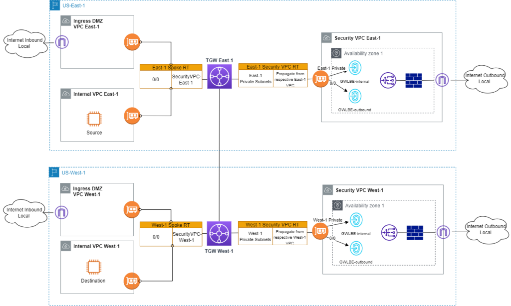
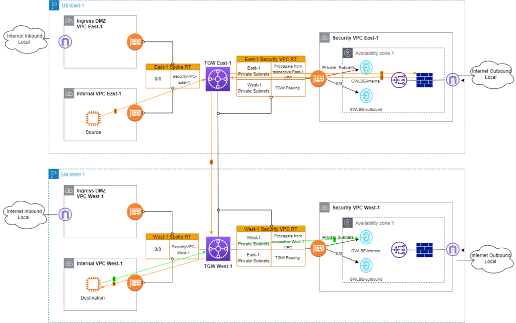
As in previous blogs, I will start with a description of the basic use case. In Figure 1, security VPC is set up with GWLB and Firewall appliances in two AWS regions, following standard deployment patterns. The two regions peer through AWS TGW. If one of the regions is only used as DR site, then the two regions can be configured in a similar way. What happens if the intention is to use the two regions in an active/active fashion? For example, an application prefers to split its components over two regions for HA purposes. There could be also some applications that have to be located in one region but have dependencies in the other region. What used to be intra-region east-west inspections now need to be extended across regions. AWS GWLB and GWLBE are regional resources. It’s not feasible to rely on GWLB to spread traffic across firewall appliances in multiple regions.
Attempt 1: Modify Spoke VPC Route Table
In the centralized design model, there are two TGW route tables involved. One is assigned to spoke VPC (those VPCs hosting workloads) attachments. The other RT is assigned to security VPC (ie hub VPC. The VPC hosts GWLB and firewall appliances) attachment. The first thought is to keep local traffic inspections to local firewalls. Only traffic to remote destinations is forwarded to firewalls in remote regions for inspection. In Figure 2, East-1 Spoke VPC RT includes new West-1 prefixes with next-hop of TGW peering. This RT is associated with East-1 TGW peering attachment. West-1 Spoke VPC RT is associated with West-1 TGW peering and contains static routes of East-1 prefixes pointing to TGW peering.
Let’s review traffic flows between a source in US-East-1 and destination in US-West-1. I am using ICMP ping as an example.
- ICMP request from source EC2 is sent to East-1 TGW.
- Per East-1 Spoke RT on TGW, traffic is put on TGW peering attachment to West-1, as destination EC2 is in West-1.
- From West-1 Spoke RT lookup, 0/0 route is used to forward traffic to West-1 Security VPC.
- Traffic is inspected by firewall and sent back to West-1 TGW.
- Traffic continues to Destination EC2.
- Destination EC2 sends ICMP response.
- Per West-1 Spoke RT, traffic is forwarded to East-1 TGW through peering attachment.
- East-1 TGW looks up East-1 Spoke RT and forwards ICMP response into East-1 Security VPC. On FW appliance, no icmp reponse is observed in traffic log, nor through packet capture. Apparently this is not due to firewall dropping ICMP response without corresponding ICMP request. Tracing backwards along the path, it’s the GWLBE-internal that I fail to find records for ICMP response. Asymmetric routing becomes an issue at underlay AWS network layer before FW complains. This follows similar observation I reported in previous blog.
Unfortunately, Attempt 1 does not work as expected. Symmetric routing is the key in GWLB/firewall design.
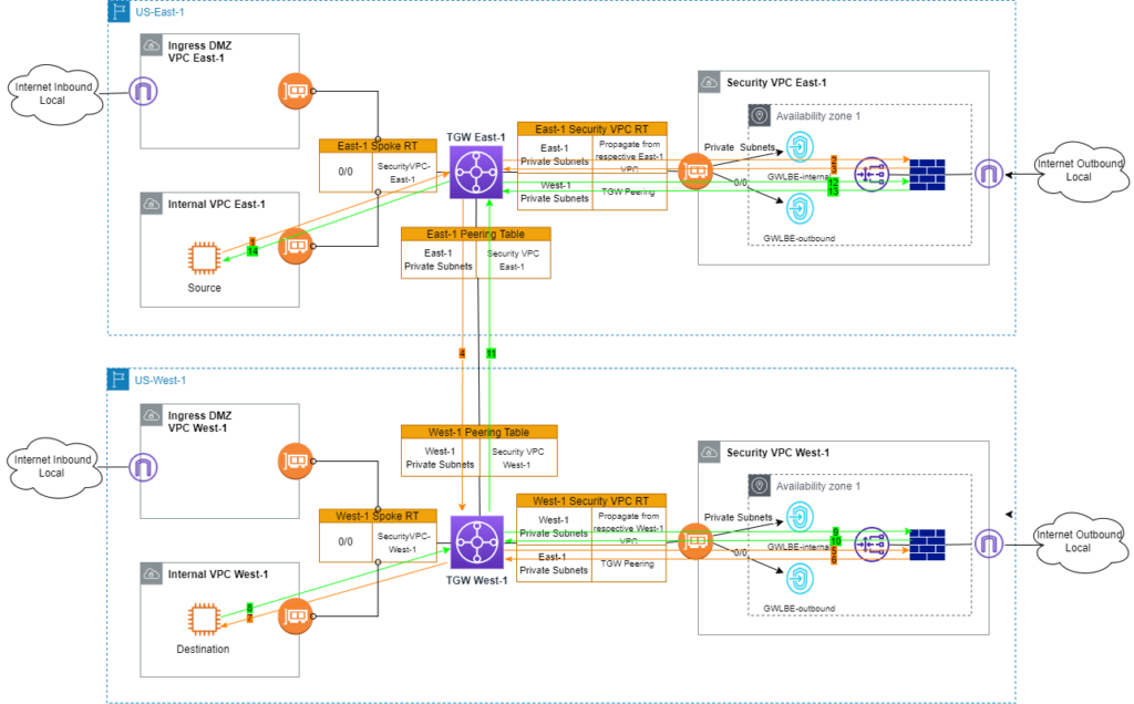
Attempt 2: Modify Security VPC Route Table
How about TGW peering attachment is changed to associate with Security VPC RT?
Let’s take another look at traffic flows.
- ICMP request from source EC2 is sent to East-1 TGW.
- Per 0/0 route in East-1 Spoke RT, traffic is sent into East-1 Security VPC.
- Traffic is inspected by firewall and back to East-1 TGW.
- East-1 TGW looks up Destination EC2 in East-1 Security VPC RT. Match is found toward TGW peering attachment.
- On West-1 TGW, West-1 Security VPC RT is consulted because TGW peering attachment is associated with this RT. ICMP request is sent to Destination EC2.
- Destination EC2 sends ICMP response.
- Per West-1 Spoke RT, ICMP response is forwarded to West-1 Security VPC. Similar to Attempt 1, traffic would stop forwarding due to asymmetric routing.
Unfortunately, it is another failed attempt due to asymmetric routing.
Attempt 3: New Peering Route Table
To work around asymmetric routing issues, new Peering route tables are introduced. In the East-1 region, Peering RT is associated with East-1 TGW peering attachment. It contains all East-1 prefixes with the next-hop of East-1 Security VPC attachment. Another change is to add new static West-1 prefixes pointing to TGW peering attachment in Security VPC RT. Route table design in West-1 follows the same enhancements.
Will the inspection work as expected this time? Let’s walk through the flows one more time.
- ICMP request from source EC2 is sent to East-1 TGW.
- Per 0/0 route in East-1 Spoke RT, traffic is sent into Security VPC in East-1.
- Traffic is inspected by firewall and back to East-1 TGW.
- East-1 TGW looks up Destination EC2 in East-1 Security VPC RT. Match is found toward TGW peering attachment.
- On West-1 TGW, West-1 Peering RT is consulted because TGW peering attachment is associated with this RT. ICMP request is sent to West-1 Security VPC.
- Traffic is inspected by firewall and back to West-1 TGW.
- Per West-1 Security VPC RT, ICMP request is forwarded to Destination EC2.
- Destination EC2 sends ICMP response.
- Per West-1 Spoke RT, ICMP response is forwarded to West-1 Security VPC.
- Traffic is inspected by firewall. So far routing is symmetric. Firewall sends traffic back to West-1 TGW.
- Per West-1 Security VPC RT, ICMP response is put on TGW peering attachment.
- Using East-1 Peering RT, traffic continues to East-1 Security VPC.
- Traffic is inspected by firewall. At this point, routing is still symmetric. FW sends response back to East-1 TGW.
- per East-1 Security VPC RT, ICMP response reaches source EC2.
Wow! Packets travel a long way between source and destination. For each direction, traffic goes through the firewall twice to meet symmetric routing requirements both at the underlay AWS network layer and firewall. At each hop, AWS flow log can be used to trace and confirm flows. It is = overwhelming the number of ENIs involved. I always note down AZ information of my source and destination. This way I can start searching flow logs on ENIs in proper AZs.
Attempt 4: One Firewall Design
In Attempt 3, firewalls from both regions are on the data path. They perform the same inspections. They do not add any additional high availability. If one region goes down, inter-region traffic is still impacted. Is there a way to remove firewalls from one side while still maintaining routing symmetry? In other words, I would need to make West-1 VPCs spokes of East-1 Security VPC for inter-region traffic. West-1 VPCs would continue using West-1 Security VPC for intra-region traffic.
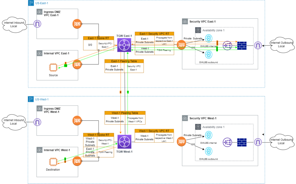
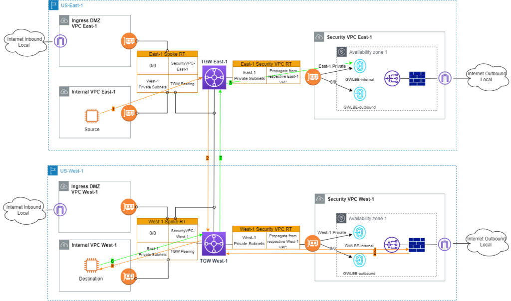
As illustrated in Attempt 3, the addition of Peering RT and its association with TWG peering attachment offers the mechanism to avoid asymmetric routing. Following the same thought processes, I tweak the Peering RT further.
Let me walk you through the new traffic flows in Figure 5.
- ICMP request from source EC2 is sent to East-1 TGW.
- Per 0/0 route in East-1 Spoke RT, traffic is sent into Security VPC in East-1.
- Traffic is inspected by firewall and back to East-1 TGW.
- East-1 TGW looks up Destination EC2 in East-1 Security VPC RT. Match is found toward TGW peering attachment.
- On West-1 TGW, West-1 Peering RT is consulted because TGW peering attachment is associated with this RT. ICMP request is sent to Destination EC2.
- Destination EC2 sends ICMP response.
- Per West-1 Spoke RT, ICMP response is forwarded to TWG peering attachment.
- Using East-1 Peering RT, traffic continues to East-1 Security VPC.
- Traffic is inspected by firewall. So far routing is still symmetric. FW sends traffic back to East-1 TGW.
- Per East-1 Security VPC RT, ICMP response reaches source EC2.
In this design, inter-region traffic only crosses the East-1 firewall. Unlike Attempt 3, the contents of East-1 and West-1 Peering tables do not mirror each other. East-1 Security VPC RT and West-1 Peering RT work together to make East-1 Security VPC the hub of West-1 VPCs. West-1 Spoke RT and East-1 Peering RT together extend West-1 VPC’s spoke role to East-1 Security VPC.
In Figure 5, either the East-1 or West-1 firewall can be used as central inspection point. I would consider traffic volume when making the choice. This example assumes West-1 has significantly more intra-region traffic. Thus East-1 firewalls are selected to serve inter-region traffic inspection.
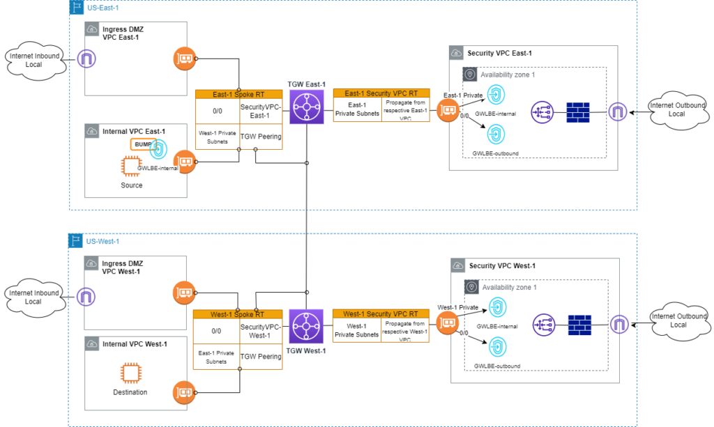
Attempt 5. Isolated Design model
In case you only have a small number of VPCs that require inter-region traffic inspection, another option is to place the “BUMP” inside the VPCs. In this approach, I don’t need to modify existing TGW RTs. All routing changes are limited to source or destination VPC.
Takeaways
In this blog, I limit the regions to two to simplify the drawings. The logic applies to multi-regions as well. I prefer to keep local exit points for Internet inbound and outbound. It’s possible to use other regions as backup path for Internet ingress/egress. However, AWS does not offer dynamic protocols. Failover will rely on manual changes.
For east-west inspection, the goal is to keep intra-region flows to the local regional firewalls. For inter-region traffic, I demonstrate how to use firewalls from a single region. In my examples, route table design assumes all inter-VPC (either intra-region or inter-region) traffic requires inspections. In your environments, you might want to adjust RT entries based on inspection needs.
I would highly recommend application design patterns that offer geo/locality support. One such solution could be GSLB. It improves application performance and reduces inter-region traffic.
In this GWLB and Palo Alto series, I covered basic mechanisms and various traffic patterns. Hope it offers good reference for your designs. Please feel free to leave comments.